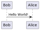
You can easily draw your PlantUML diagrams in Markdown with the following syntax
$$uml

Bob -> Alice: Hello World!

$$
It will be rendered like this
Activity Diagram
$$uml
partition Conductor {
  (*) --> "Climbs on Platform"
  --> === S1 ===
  --> Bows
}
partition Audience #LightSkyBlue {
  === S1 === --> Applauds
}
partition Conductor {
  Bows --> === S2 ===
  --> WavesArmes
  Applauds --> === S2 ===
}
partition Orchestra #CCCCEE {
  WavesArmes --> Introduction
  --> "Play music"
}
$$
It will be rendered like this
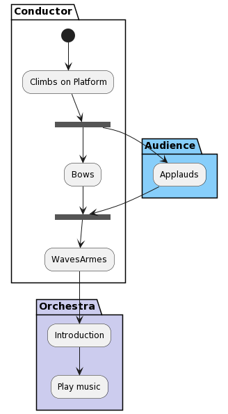
More examples of the Activity Diagram
Class Diagram
$$uml
abstract        abstract
abstract class  "abstract class"
annotation      annotation
circle          circle
()              circle_short_form
class           class
diamond         diamond
<>              diamond_short_form
entity          entity
enum            enum
interface       interface
protocol        protocol
struct          struct
$$
It will be rendered like this
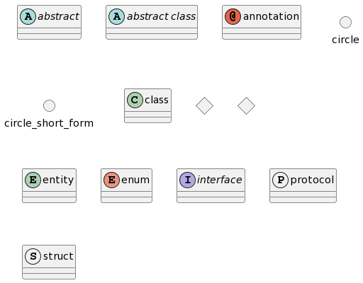
More examples of the Class Diagram
Component Diagram
$$uml
package "Some Group" {
  HTTP - [First Component]
  [Another Component]
}
node "Other Groups" {
  FTP - [Second Component]
  [First Component] --> FTP
}
cloud {
  [Example 1]
}
database "MySql" {
  folder "This is my folder" {
    [Folder 3]
  }
  frame "Foo" {
    [Frame 4]
  }
}
[Another Component] --> [Example 1]
[Example 1] --> [Folder 3]
[Folder 3] --> [Frame 4]
$$
It will be rendered like this
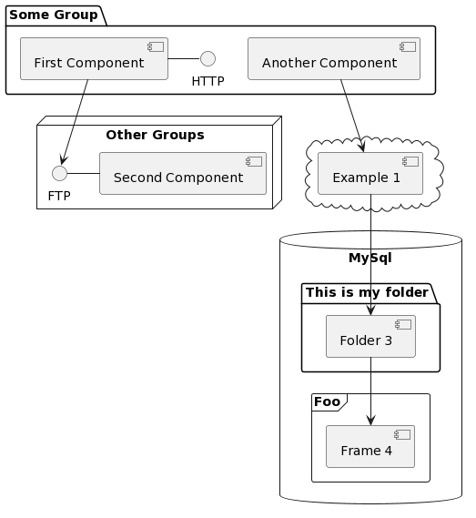
More examples of the Component Diagram
Object Diagram
$$uml
left to right direction
' Horizontal lines: -->, <--, <-->
' Vertical lines: ->, <-, <->
title PERT: Project Name

map Kick.Off {
}
map task.1 {
    Start => End
}
map task.2 {
    Start => End
}
map task.3 {
    Start => End
}
map task.4 {
    Start => End
}
map task.5 {
    Start => End
}
Kick.Off --> task.1 : Label 1
Kick.Off --> task.2 : Label 2
Kick.Off --> task.3 : Label 3
task.1 --> task.4
task.2 --> task.4
task.3 --> task.4
task.4 --> task.5 : Label 4
$$
It will be rendered like this
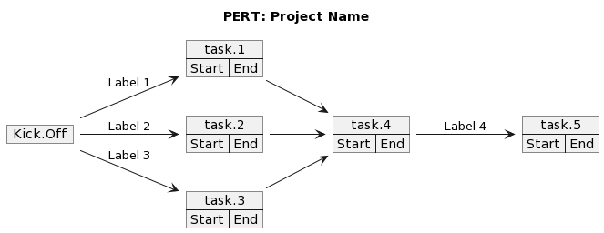
More examples of the Object Diagram
Sequence Diagram
$$uml
participant Participant as Foo
actor       Actor       as Foo1
boundary    Boundary    as Foo2
control     Control     as Foo3
entity      Entity      as Foo4
database    Database    as Foo5
collections Collections as Foo6
queue       Queue       as Foo7
Foo -> Foo1 : To actor
Foo -> Foo2 : To boundary
Foo -> Foo3 : To control
Foo -> Foo4 : To entity
Foo -> Foo5 : To database
Foo -> Foo6 : To collections
Foo -> Foo7: To queue
$$
It will be rendered like this
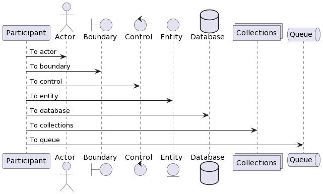
More examples of the Sequence Diagram
State Diagram
$$uml
state start1  <<start>>
state choice1 <<choice>>
state fork1   <<fork>>
state join2   <<join>>
state end3    <<end>>
[*]     --> choice1 : from start\nto choice
start1  --> choice1 : from start stereo\nto choice
choice1 --> fork1   : from choice\nto fork
choice1 --> join2   : from choice\nto join
choice1 --> end3    : from choice\nto end stereo
fork1   ---> State1 : from fork\nto state
fork1   --> State2  : from fork\nto state
State2  --> join2   : from state\nto join
State1  --> [*]     : from state\nto end
join2   --> [*]     : from join\nto end
$$
It will be rendered like this
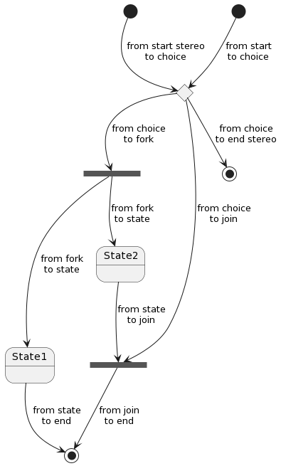
More examples of the State Diagram
Use Case Diagram
$$uml
left to right direction
actor Guest as g
package Professional {
  actor Chef as c
  actor "Food Critic" as fc
}
package Restaurant {
  usecase "Eat Food" as UC1
  usecase "Pay for Food" as UC2
  usecase "Drink" as UC3
  usecase "Review" as UC4
}
fc --> UC4
g --> UC1
g --> UC2
g --> UC3
$$
It will be rendered like this
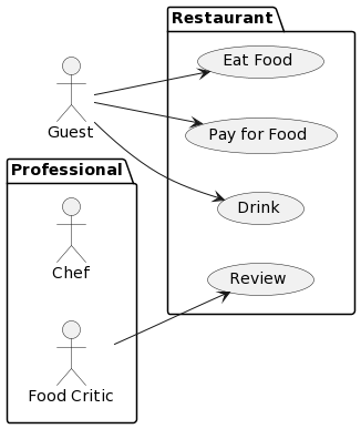
More examples of the Use Case Diagram